Top Problems with PV Combiner Boxes and How to Troubleshoot Them
Stop guessing and start diagnosing. This guide distills the most common PV combiner box failures and provides step‑by‑step procedures, tool lists, and decision trees to get your array safely back online—fast.
PV Safety
O&M
1500V DC
Introduction
PV combiner boxes aggregate multiple PV strings, provide overcurrent and surge protection, and present a safe interface to the inverter. Because they collect fault energy from parallel strings and often operate in harsh outdoor environments, failures tend to concentrate here first. A disciplined troubleshooting approach protects people and assets while minimizing production losses.
Quick Symptom → Likely Cause Map
| Field Symptom | Most Likely Causes | First Checks |
|---|---|---|
| String current = 0 A | Blown fuse, open circuit, loose terminal, MC4 not latched | Fuse continuity, connector seating, polarity, conductor continuity |
| Frequent SPD alarms / indicator red | SPD cartridge end‑of‑life, wrong Uc, poor earthing | Visual SPD flag, earth continuity, surge history |
| Hot smell, discoloration near lugs | Loose torque, undersized cable, corrosion | IR scan, torque check, inspect for soot |
| Water droplets inside cover | Ingress via glands, missing breather, gasket damage | IP checks, gland tightness, add breather/replace gasket |
| No data from smart combiner | Power loss, RS‑485 mis‑termination, address conflict, firmware fault | Aux supply, bias resistors, node address, reboot module |
Essential Tools & PPE
Measurement
- DC clamp meter (low‑amp accuracy for string current)
- True‑RMS multimeter (CAT III/IV, DC‑rated)
- Insulation resistance tester (up to system voltage)
- Thermal camera (hotspot detection)
Service
- Torque wrench & torque screwdriver with log sheet
- Crimping tools and ferrules/lugs matched to cable
- Spare gPV fuses, SPD cartridges, gland seals
- Cleaning kit: brush, lint‑free wipes, isopropyl alcohol
PPE
- Arc‑rated clothing & DC‑rated insulated gloves
- Face shield, safety glasses, hearing protection
- Lockout/tagout kit and warning signage
Problem #1: Blown Fuses / Tripped DC Breakers
String fuses protect conductors from fault currents contributed by parallel strings. Repeated fuse operations indicate an underlying issue rather than a simple nuisance trip.
Common Causes
- String short (damaged cable, junction box fault)
- Module bypass diode failure causing reverse current
- Reverse polarity connection during maintenance
- Undersized fuse rating vs. worst‑case current
Diagnostics: Step‑by‑Step
Corrective Actions
- Replace damaged conductors/connectors; reroute to avoid abrasion points
- Replace failed modules or diode assemblies per OEM procedure
- Recalculate fuse sizing; consider next standard rating if borderline (within code)
- Document root cause and update maintenance logs
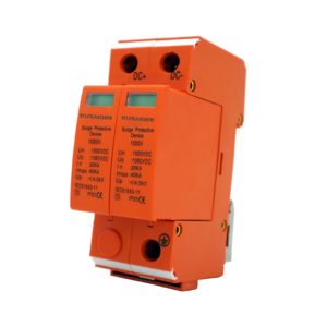
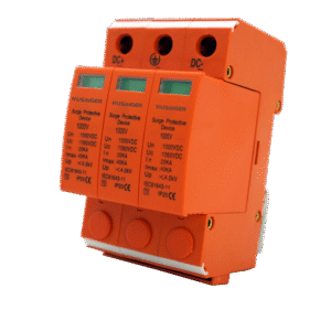
Problem #2: SPD End‑of‑Life or Mis‑Specification
DC SPDs protect against surges from lightning or switching events. They wear out as their protective elements absorb energy.
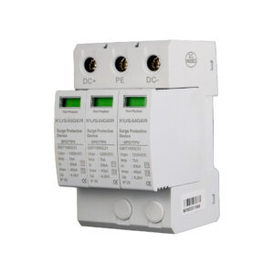
Red Flags
- Indicator window shows red / fault
- Repeated site‑wide SPD failures after storms
- Unexpected trips of upstream protective devices
Triage Procedure
- Verify Uc (continuous operating voltage) ≥ system max operating voltage.
- Check earthing & bonding: measure earth resistance; inspect terminations.
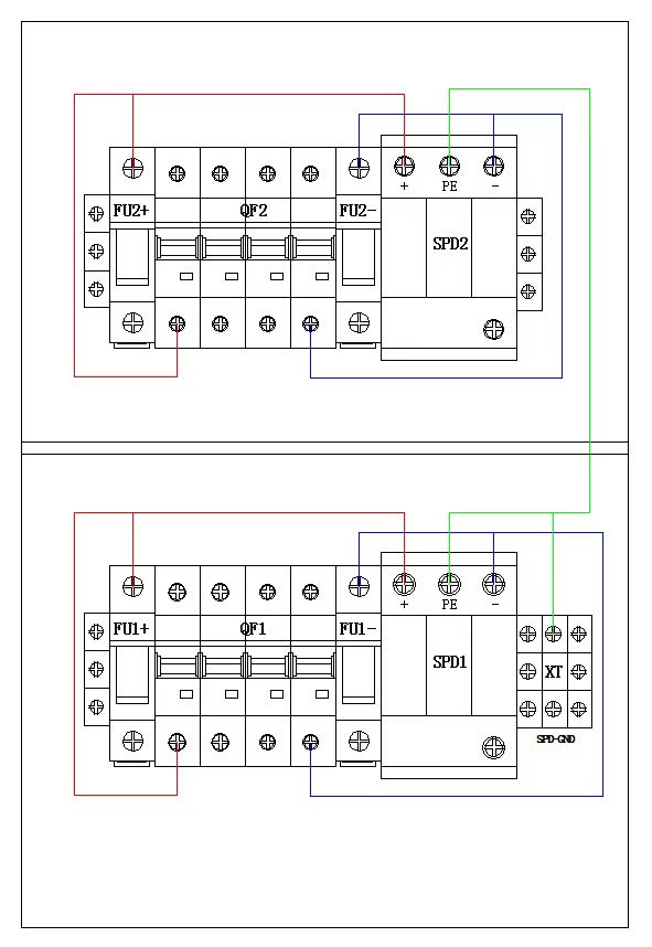
- Replace cartridge modules with OEM parts; confirm correct mode (+/− to PE).
- Evaluate site lightning density; upgrade to Type 1+2 if warranted.
Best Practices
- Keep spare cartridges on site; log replacement dates
- Short, straight leads to minimize inductance
- Bond enclosure and negative/positive per earthing scheme
Problem #3: Loose Terminations & Overheating
Thermal cycles loosen lugs; even small increases in resistance can create hotspots that escalate into failures.
Symptoms
- Browned insulation, odor, or melted plastic near terminals
- IR camera shows ΔT > 20–30 °C vs. ambient or peers
- Intermittent performance drops during midday peaks
How to Detect & Fix
- Perform IR scan at high irradiance; mark hotspots.
- De‑energize, then re‑torque per manufacturer spec; apply torque seal paint.
- Inspect for corrosion; clean with approved solvents; replace heat‑damaged parts.
- Confirm conductor size and ferrule/lug selection; re‑crimp if necessary.
Problem #4: Water Ingress, Condensation & Corrosion
Ingress compromises insulation and rapidly destroys metal parts. Coastal, desert (sand), and humid regions need extra attention.
Root Causes
- Loose glands, wrong gland size vs. cable OD
- Damaged or aged door gaskets; missing pressure equalization vents
- Improper mounting orientation or low mounting height (splash/flood)
Remediation
- Open, dry the enclosure; replace corroded parts and terminals.
- Install/descale breather vents to limit condensation.
- Replace all gaskets; re‑land glands to rated torque; apply UV‑stable sealant if approved.
- Consider canopies or sunshades; raise mounting height above splash zone.
Prevention Checklist
- Specify IP65+ / NEMA 4X with corrosion‑resistant hardware
- Use UV‑stable cable jackets; avoid downward loops that wick water inside
- Add desiccant packs and inspect quarterly in humid climates
Problem #5: Monitoring & Communication Failures
Smart combiners add per‑string current sensors and temperature points. When data goes dark, fault localization slows.
Likely Causes
- Aux power loss to the monitoring module
- RS‑485 wiring errors (polarity, termination, shielding)
- Address conflicts or wrong baud/parity settings
- Firmware lockup due to brownouts
Stepwise Checks
- Verify auxiliary supply voltage/current; check fuses.
- Inspect A/B polarity, shield drain bonding at one end only.
- Ensure only the two end nodes have termination resistors.
- Check device address map; resolve duplicates; reboot endpoints.
- Capture a baseline after fix; trend data for 7–14 days.
Other Issues (Ground Faults, Arc Faults, Isolation)
- Ground faults: Insulation deterioration or damaged cables. Use insulation resistance testing string‑by‑string; inspect routes for abrasion.
- Arc faults: Intermittent connections creating series arcs. Look for pitted contacts, carbonization; replace suspect components and enforce strain relief.
- Isolation faults at high humidity: Dry the enclosure, retest IR, and review creepage/clearance around busbars.
Universal Troubleshooting Procedure
- Make safe: LOTO, verify zero energy state, install barriers.
- Gather evidence: Site history, weather, event logs, alarms.
- Non‑intrusive tests: Visual, IR scan, external measurements.
- Isolate and test: One string at a time—Voc, Isc, insulation.
- Repair/replace: Use OEM parts and documented torque/specs.
- Functional test: Re‑energize gradually; verify currents match baseline.
- Document: Root cause, photos, measurements, actions, and spares used.
Target MTTR
Aim to localize to the string within 60 minutes and restore service within 4 hours for typical faults.
Thermal KPI
ΔT at any lug < 15 °C vs. peer terminals under similar load.
Documentation
100% of interventions logged with torque values and IR images.
Preventive Measures & PM Program
Routine PM (Suggested)
| Frequency | Actions |
|---|---|
| Monthly | Visual checks; clean dust; verify door seals; check SPD indicators. |
| Quarterly | Torque check critical lugs; IR scan at noon; verify monitoring data integrity. |
| Semi‑Annual | Replace desiccants; test insulation; sample fuse continuity. |
| Annual | Comprehensive inspection; replace aged SPDs/fuses as per OEM; gasket replacement if brittle. |
Design & Procurement Tips
- Specify IP65+/NEMA 4X, IK10, UV‑stable materials for harsh sites
- Choose metal enclosures for better thermal handling; polycarbonate for corrosion resistance
- Include breather vents and sunshades in BOM for humid/hot climates
- Prefer smart combiners with per‑string measurement for faster diagnostics
Data‑Driven O&M
- Track per‑string current variance (σ) to trigger cleaning or vegetation control
- Set alarms for SPD status, ΔT thresholds, and breaker status
- Use QR‑coded as‑builts for instant access to wiring diagrams on site
Frequently Asked Questions
Can I upsize fuses to stop nuisance blows?
Only within design and code limits. Nuisance blows usually indicate a real issue—check wiring, diode health, and current calculations before upsizing.
How do I know which SPD type to use?
Type 2 covers many sites. Use Type 1 or Type 1+2 in high lightning density or when direct currents are possible. Ensure Uc exceeds max operating voltage.
What ΔT is acceptable on terminals?
Target < 15 °C vs. peers under similar load. Anything above 20–30 °C warrants investigation.
Do I need monitoring?
Per‑string monitoring reduces MTTR and improves yield by early fault detection—highly recommended for C&I and utility plants.
Downloadable Checklists