Installation Best Practices and Safety Requirements for Photovoltaic Combiner Boxes
Practical installation guide for PV installers, EPC contractors and O&M teams.
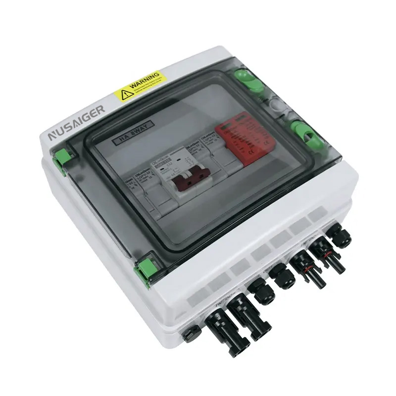
Overview
Photovoltaic (PV) combiner boxes are key balance-of-system components that consolidate outputs from multiple PV strings, provide string-level protection, and house surge protection and monitoring equipment. Proper installation and adherence to safety requirements are essential to ensure long-term reliability, reduce fire risk, and simplify maintenance. This article presents a step-by-step installation guide, safety considerations, testing & commissioning steps, common mistakes to avoid, and post-installation inspection checklists.
1. Pre-Installation Planning
Thorough planning reduces rework and improves safety. Before field work begins, complete the following:
- Review design documents: single-line diagrams, string layouts, electrical load calculations, and combiner box datasheets.
- Confirm site conditions: mounting surfaces, distance from array to inverter, exposure (UV, salt spray, dust), and available clearances for O&M access.
- Procure correct equipment: combiner box model, SPDs, fuses/breakers, glands, busbar connectors, and spare parts.
- Verify electrical ratings: Voc, Isc per string, maximum output current, and AC/DC isolation requirements.
- Safety planning: LOTO procedure, arc-flash assessment, PPE requirements, and task-specific risk assessment (JSA/Safe Work Permit).
- Tooling & consumables: calibrated torque wrenches, insulated tools, thermal camera, megohmmeter, multimeter, anti-oxidant paste (for aluminium joints), and sealant for cable glands.
2. Choosing Installation Location & Mounting
2.1 Proximity to arrays
Install combiner boxes as close to the PV modules as practical to minimize DC cable length and voltage drop. Shorter runs reduce resistive losses and lower material costs.
2.2 Accessibility and service space
Provide adequate clearance around the combiner box for safe access: minimum ~600 mm (local codes may vary) in front for service, and secure mounting height for technician ergonomics.
2.3 Mounting hardware
Use corrosion-resistant mounting brackets (stainless steel or galvanized) and vibration-damping pads on tracker mounts. Ensure the supporting surface can bear the static and dynamic loads.
2.4 Environmental protection
Select IP/NEMA-rated enclosures appropriate for the site (IP65/NEMA 4X for outdoor rooftop and harsh conditions). Consider sunshades or ventilated cabinets for high-irradiance locations.
3. Cabling and Conduit Best Practices
3.1 Conductor routing
Plan conductor routes to avoid running DC positive and negative conductors parallel to AC conductors where possible and prevent interference. Maintain mechanical protection for cables where they pass through rooftops or exposed areas.
3.2 Cable size and ampacity
Size PV DC conductors for continuous current rating plus temperature correction and grouping factors per national code (e.g., NEC). Consider voltage drop limits — for long runs, upsize conductors to keep losses acceptable.
3.3 Cable glands and entry sealing
Use UV-resistant, PV-rated cable glands sized correctly for conductor outer diameter. Apply appropriate thread sealant or gaskets to maintain the combiner box ingress protection. Tighten glands per manufacturer torque guidance.
3.4 Bending radius and strain relief
Respect minimum bending radii for PV cables to avoid conductor stress. Provide strain relief and secure cable bundles to reduce mechanical load on terminations.
4. Terminations, Busbars and Torque Control
4.1 Busbar material and plating
Most combiner box busbars are tin-plated copper for corrosion resistance and solderability. For coastal sites, ensure proper plating thickness and corrosion-resistant fasteners.
4.2 Preparation of cable ends
Use appropriate ferrules or lugs rated for DC PV application. Crimp or solder per manufacturer instructions. Inspect each termination for correct installation.
4.3 Torque values and documentation
Tighten bolted terminations to manufacturer-specified torque using calibrated torque wrenches. Record torque values in commissioning documentation. Over-torquing crushes busbars; under-torquing leads to hot-joints.
Tip: Create a torque matrix
Document torque values for each bolt size used (e.g., M6 = 8 Nm, M8 = 22 Nm) and include it inside each combiner box manual pouch.
5. Overcurrent Protection: Fuses and Breakers
5.1 Fuse vs breaker selection
String-level protection typically uses PV-rated fuses (cylindrical or cartridge) or DC-rated breakers. Fuses are compact and cost-effective; breakers are resettable and improve O&M convenience. Select devices with proper interrupt ratings and DC characteristics.
5.2 Sizing fuses
Follow code (e.g., NEC 690.8 guidance) and manufacturer instructions. A common practice: fuse rating ≥ Isc × safety factor (consult local regulations) but ≤ conductor ampacity to ensure protection.
5.3 Mounting and replacement access
Design fuse holders or breaker access to be replaceable without opening hazardous areas when possible. Provide clear labeling for fuse types and spares to minimize downtime.
6. Surge Protection and Grounding
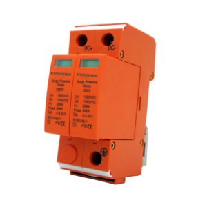
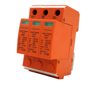
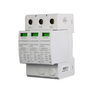
6.1 SPD selection for PV DC
Install SPDs rated for DC operation and matched to system Voc (600V/1000V/1500V). Choose devices with appropriate In/Imax, clamping voltage (Up), and thermal disconnect features. In lightning-prone regions, deploy coordinated multi-level protection: array-level SPDs at combiner boxes and point-of-entry SPDs at inverter or service entrance.
6.2 Grounding best practices
Short, low-impedance ground conductors are essential. Bond combiner enclosures, negative bus, and local ground rods to the site ground system and equipotential mesh. Use appropriate conductor sizes for grounding per code. Never rely on conduit as the primary grounding conductor unless designed for that purpose.
6.3 Equipotential bonding
For modules, racking, combiner enclosures and inverter enclosures, ensure equipotential bonding to prevent potential differences that cause damage during surge events.
7. Enclosure Sealing, Ventilation & Thermal Management
7.1 Sealing against ingress
Confirm that gaskets, cover screws, and cable glands preserve the stated IP rating. For hot climates, seal to reduce dust ingress and prevent moisture condensation inside the enclosure.
7.2 Ventilation
Combiner boxes with internal electronics or SPDs may require ventilation. Passive vents with insect filters can be used; in extreme heat, consider shaded mounting and reflective paint to reduce thermal load.
7.3 Thermal design considerations
Ensure busbar sizing accounts for temperature derating. Locate temperature-sensitive components (e.g., SPDs) away from hot spots and provide thermal monitoring if necessary.
8. Labeling, Documentation and Lockable Access
Label every string input, polarity, fuse/breaker ID, voltage class, and main output clearly. Keep wiring diagrams and component lists in a sealed pouch inside the combiner box or at a protected O&M station. Provide lockable covers and key-controlled access where safety or theft risk exists.
9. Commissioning Tests & Verification
Commissioning ensures safe operation before tying into the inverter or grid. Perform the following tests in sequence:
9.1 Visual inspection
- Correct model and parts installed
- No loose wires, damaged insulation or foreign objects
- Glands and seals properly installed
9.2 Electrical tests
- Continuity and low resistance: milliohm checks across busbars and output connections
- Insulation resistance: megger test between positive, negative and earth per manufacturer recommendations
- Polarity and VOC checks: verify string polarity and open-circuit voltage at inputs
9.3 Thermal baseline
Capture thermographic images under load or simulated load to establish baseline hotspots. Use this as reference for future maintenance.
9.4 Functional checks
- Verify SPDs show green/healthy indicators (if available)
- Validate monitoring telemetry (Modbus registration, alarms, and timestamps)
- Test operation of switches and visible isolators
9.5 Documentation & handover
Record all test results, torque readings, serial numbers of SPDs and fuses, and commissioning photos. Provide handover packet to the O&M team.
10. Safety Protocols during Installation
Adhere to safe work practices throughout:
- Implement Lock Out Tag Out (LOTO) on DC circuits before work
- Wear appropriate PPE: insulating gloves, arc-rated clothing when necessary, eye protection, and fall protection for rooftop work
- Only qualified personnel should perform live testing; minimize live exposure time and maintain safe distances
- Use insulated tools and follow tool calibration program
- Maintain a site-specific emergency plan (first aid, rescue, nearest medical facility)
11. Common Installation Errors and How to Avoid Them
- Loose terminations: Always use torque wrenches and record values; implement retorque schedule.
- Incorrect fuse sizing: Verify Isc, choose correct fuse type and avoid substituting non-PV rated parts.
- Poor gland sealing: Use correct gland type and apply sealants as required; test ingress protection after installation.
- Long ground leads: Keep grounding conductors short and low-impedance; avoid looping grounds.
- Unlabeled inputs: Label during installation to simplify debugging and O&M.
12. Post-Installation Handover and O&M Preparation
Deliverables to hand to O&M team:
- As-built wiring diagrams and single-line diagrams
- Torque log and test certificates
- SPD and fuse serial numbers and replacement part list
- Monitoring and SCADA connection details (IP, baud rate, modbus map)
- Maintenance checklist and recommended inspection intervals
13. Sample Inspection & Commissioning Checklist (Printable)
Combiner Box Commissioning Checklist
-----------------------------------
Location: __________________________
Combiner Model: ____________________
Voltage Class (Voc): _______________
Inputs (count): ____________________
Installer: _________________________
Date: _____________________________

Pre-Installation:
- Site risk assessment completed
- Tools and PPE verified

Mounting & Mechanical:
- Enclosure mounting secure
- Gland and seals fitted
- Access clearance ok

Electrical Tests:
- Continuity/milliohm readings recorded
- Insulation resistance (MΩ) recorded
- Polarity & Voc checked
- Torque values logged (see attached)
- SPDs green/functional

Thermal:
- Thermographic images captured (baseline)

Documentation:
- Diagrams, part lists included
- Commissioning report completed

Sign-off:
Installer: ___________   Date: _____
O&M rep: _____________  Date: _____
14. Useful References and Standards
- NEC Article 690 — Photovoltaic Systems (U.S.)
- IEC 61730 & IEC 62548 — PV module and array design
- IEC 61643 series — Surge protective devices (SPDs)
- Manufacturer installation manuals and torque matrices
15. Conclusion & Key Takeaways
Professional installation of photovoltaic combiner boxes reduces operational risk and maximizes system uptime. Key points:
- Plan thoroughly before work: parts, tools, safety and documentation.
- Prioritize short DC runs, proper gland sealing, accurate torqueing and robust grounding.
- Use PV-rated components (fuses, glands, SPDs) and adhere to applicable standards.
- Capture commissioning baselines (thermal, torque, insulation) and hand over complete documentation to O&M.
Following these practices helps ensure safer, more reliable PV installations and simplifies future maintenance and troubleshooting.