Photovoltaic Busbars: Comprehensive Technical & Application Guide — Design, Installation, Maintenance, and Future Trends
Complete guide for PV engineers, system designers, installers, and O&M teams.
Table of Contents
- Introduction & Definitions
- Role of Busbars in Photovoltaic Systems
- Types and Materials
- Electrical & Thermal Design Principles
- Mechanical Design & Manufacturing Methods
- Standards, Codes, and Certification
- Installation Best Practices and Site Layout
- Testing, Commissioning, and Acceptance
- Maintenance, Inspection & Troubleshooting
- Common Failures and Case Studies
- Performance Optimization in Different Environments
- Costs, Procurement and Supply-chain Considerations
- Future Trends: Materials, Automation, & Sustainability
- Practical Checklists & Quick Reference Tables
- Conclusion & Key Takeaways
1. Introduction & Definitions
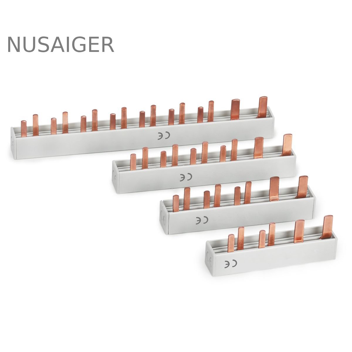
A busbar (also spelled bus bar) in photovoltaic (PV) systems is a conductor or ensemble of conductors that collects and distributes DC current generated by solar modules. In the context of PV arrays, “busbar” refers to multiple scales of hardware:
- Cell/Module Busbars: thin copper (or printed) strips that connect PV cells inside a module (commonly 2–9 busbars per cell string in modern modules).
- String Busbars: heavier conductors inside combiner boxes that combine multiple module strings.
- Array/Main Busbars: large-capacity copper or aluminium bars that collect current from multiple combiner boxes before the inverter.
This guide uses “busbar” to cover mid-to-large scale conductive distribution elements in PV systems — from internal module conductors up to utility-scale DC collection busbars.
Why busbars matter
Busbars are a deceptively simple part of the system yet directly impact:
- Electrical efficiency (resistive losses)
- System safety (short-circuit, thermal runaway, arc faults)
- Mechanical reliability (vibration, thermal cycling)
- Installation cost and maintainability
The remainder of the article dives into design, material selection, testing, installation, and long-term operation strategies.
2. Role of Busbars in Photovoltaic Systems
In PV plants the function of busbars can be summarized in three roles:
- Collection: Aggregate current from module strings or combiner boxes.
- Distribution: Distribute DC power to inverters, DC disconnects, and energy storage systems.
- Protection interface: Host or integrate protection and monitoring devices — fuses, SPD mounts, current sensors, disconnects.
Where busbars are used (typical architectures)
Common PV plant architectures using busbars:
- Rooftop commercial systems: Short string busbars inside rooftop combiner enclosures to reduce conduit runs.
- Ground-mounted utility arrays: Field busbar trenches or overhead busbar trenches collect cluster outputs.
- Centralized inverters: Heavy busbars in DC yard to carry combined current to central inverters.
Advantages vs cable-only solutions
Using busbars instead of multiple parallel cables offers:
- Lower resistance per cross-sectional area for the same footprint
- Reduced inductance compared to bundled cables — important for transient behavior
- Simpler mechanical support and routing
- Modular expansion and easier maintenance access
3. Types and Materials
Choice of busbar type and material depends on current rating, environment, mechanical constraints and cost. Common materials:
3.1 Copper (electrolytic copper, OFHC)
Advantages: highest conductivity (≈59.6 MS/m), excellent mechanical strength, ease of soldering and tinning. Widely used for module busbars (thin copper ribbons) and medium-size busbars (≥10–200 A).
Disadvantages: heavier than aluminium and more expensive; requires corrosion protection in aggressive environments.
3.2 Tinned copper
Tinning improves solderability and corrosion resistance — common for module ribbons and exposed busbars in coastal zones. Tin plating is recommended where surface oxidation would compromise connection resistance over time.
3.3 Aluminium (AA series)
Advantages: cost-effective, light weight, adequate conductivity when sized correctly (≈35–37 MS/m). Frequently used in high-current, long-run overhead busbars.
Disadvantages: more prone to galvanic corrosion when contacting copper; requires special connectors and anti-oxidation measures; lower mechanical strength per cross-section.
3.4 Copper-clad aluminium (CCA)
Hybrid option with aluminium core and copper cladding — combines light weight and improved conductivity for contact surfaces. Common for economized long runs, but cladding thickness control is critical.
3.5 Advanced materials
Research and niche products include silver-plated busbars (for ultra-low contact resistance), composite busbars with polymer insulation, and flexible printed busbars for module-level interconnects. These are used where performance or miniaturization justifies cost.
Material selection checklist
- System DC voltage and maximum current (steady state and short-circuit current)
- Ambient temperature and exposure (UV, salt spray, industrial gasses)
- Mechanical constraints (weight, profile, support)
- Corrosion risk & required lifespan (10–30+ years)
- Maintenance access and ease of replacement
4. Electrical & Thermal Design Principles
Design of a busbar must ensure minimal resistive losses, acceptable temperature rise, reliable short-circuit performance, and low electrical noise. This section covers calculations, thermal considerations and examples.
4.1 Resistive losses and cross-sectional sizing
Resistive (I²R) losses depend on conductor resistance (R) and current (I). Design target is to keep voltage drop acceptable (commonly <1–2% for DC collector circuits) and limit steady-state temperature.
Resistance calculation
Resistance R = ρ * L / A
- ρ = resistivity of material (Ω·m)
- L = length (m)
- A = cross-sectional area (m²)
Example: copper busbar 10 mm × 2 mm (A = 20 mm² = 2.0e-5 m²), length 2 m, ρ (copper) ≈ 1.724e-8 Ω·m
R = 1.724e-8 * 2 / 2e-5 = 0.001724 Ω
If current I = 20 A, loss P = I²R = 400 * 0.001724 = 0.6896 W. Voltage drop = I * R = 20 * 0.001724 = 0.03448 V (very low).
4.2 Temperature rise and thermal management
Joule heating raises busbar temperature; thermal design ensures the operating point stays below material and insulation limits. Use conservative ambient temperature and maximum current for worst-case analysis.
Thermal steady-state requires dissipated heat to be balanced by convection and radiation. Empirical tables or finite-element thermal modeling are standard for precision designs.
4.3 Short-circuit and mechanical stresses
Busbars must withstand electromagnetic forces during short-circuit events. Peak mechanical force F between parallel conductors can be estimated as:
F ≈ (μ0 * I1 * I2 * L) / (2π * d)
Where μ0 is permeability (4πe-7 H/m), d is center-to-center distance. Proper bracing and supports mitigate deflection and fatigue.
4.4 Skin and proximity effects (AC context)
AC systems require consideration of skin effect at high frequencies; for PV DC busbars this is generally negligible — but if busbars carry AC (e.g., in inverter DC link or microgrids) consider effective resistance increase at switching frequencies.
4.5 Busbar geometry and footprints
Common profiles: flat strips, rectangular bars, hollow sections for weight saving, laminated busbars for insulation and compactness. Laminated busbars (copper core with insulating layers) reduce footprint and are widely used inside power electronics.
4.6 Contact resistance and termination design
Contact resistance at bolted joints dominates losses in many systems. Use large contact areas, proper torque values, anti-oxidation compounds (for aluminum), and periodic retorqueing per maintenance schedule.
5. Mechanical Design & Manufacturing Methods
Manufacturing method influences tolerances, surface finish, and cost. Key processes include stamping, extrusion, CNC machining, and lamination.
5.1 Stamped busbars
Stamping from sheet copper is low-cost for high-volume medium-current parts (module ribbons, small combiner bar segments). Good for complex flat shapes and pre-drilled mounting holes.
5.2 Extruded busbars
Aluminium or copper extrusion produces continuous lengths with controlled cross-section — ideal for larger current-carrying rails and long runs.
5.3 CNC machined busbars
Used when tight tolerances, holes, and 3D geometry are required (e.g., busbar assemblies inside high-power DC combiner units). More expensive but precise.
5.4 Laminated busbars (flex & rigid)
Manufactured by laminating copper foils between insulating layers (polyimide, epoxy). Offer compact layout for switchgear and power electronics; reduce loop inductance and improve thermal dissipation.
5.5 Surface treatments and plating
Tinning, silver plating, or nickel plating improve corrosion resistance and solderability. For aluminium, anodizing or protective coatings are used. Surface finish impacts contact reliability and ageing.
5.6 Insulation & encapsulation
Busbars are insulated using heat-shrink tubing, insulated saddles, thermoset paints, or molded polymer housings. Weatherproof enclosures are essential at the array level.
6. Standards, Codes, and Certification
Design and installation must follow applicable electrical and building codes and standards. Relevant standards include:
- IEC 61439 — Low-voltage switchgear and controlgear assemblies (busbar enclosures, current-carrying capacity testing).
- IEC 62548 — Photovoltaic arrays — Design requirements.
- NEC Article 690 (U.S.) — Solar photovoltaic systems (DC and AC conductors, fusing, junctions).
- UL 1703 / UL 61730 — PV modules and components.
- IEC 60364 — Electrical installations of buildings (grounding conventions).
Compliance with recognized third-party testing and certification (UL, CE, TÜV) improves reliability, safety, and project approval speed.
7. Installation Best Practices and Site Layout
Installation quality is often the difference between a reliable system and one with recurring issues. Below are best practices derived from field experience.
7.1 Pre-installation planning
- Map cable runs and busbar locations early in design to minimize conductor lengths and avoid later rework.
- Coordinate with structural engineers for mounting loads and anchor points.
- Specify clear access for O&M (service aisles, hinged access panels).
7.2 Mounting and supports
Use non-conductive saddles or insulated standoffs where busbars pass through or near structures. Allow thermal expansion gaps for long runs. Design for vibration damping in tracker-mounted arrays.
7.3 Mechanical and electrical terminations
Torque bolts to manufacturer specs and document torque values. Use lockwashers or torque retention methods to mitigate loosening from thermal cycling. For aluminium conductors, apply antioxidant pastes and special connectors to prevent galvanic corrosion with copper hardware.
7.4 Grounding & equipotential bonding
Ensure dedicated grounding bus is sized per code. Bond metal enclosures, supports, and busbars to the grounding network. Consider a separate equipotential bus for lightning protection bonding.
7.5 Environmental protection
Deploy IP65+ enclosures for outdoor combiner busbar boxes; ensure cable glands and gaskets are rated. In coastal or industrial atmospheres, specify stainless steel or polymer enclosures to resist corrosion.
7.6 Lightning & surge mitigation
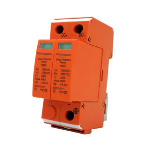
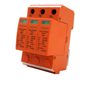
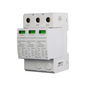
Install surge protective devices at combiner boxes and at the DC bus if required. Implement proper surge grounding (short, low-impedance earth connections) and bonding to facility ground rods or mesh.
8. Testing, Commissioning, and Acceptance
Before energizing a PV installation, perform comprehensive testing:
8.1 Visual inspection checklist
- Confirm correct busbar sizes and part numbers
- Check torque values on all bolted joints
- Verify insulation and gaskets intact
- Ensure labeling and polarity markers are present
8.2 Electrical tests
- Continuity & resistance: Verify low-resistance connections using micro-ohm or milliohm meters.
- Insulation resistance: Use megohmmeter to test isolation between conductors and ground.
- Polarity & open-circuit checks: Confirm string polarity before connection to busbars.
- Thermographic baseline: Run inverter or simulated load and record thermal images to capture hot-spots.
8.3 Functional verification
Test that monitoring sensors on busbars (if present) report correctly to SCADA. Check SPDs and disconnects operate as expected. Verify alarms and logging are functional.
8.4 Acceptance criteria
Define clear acceptance metrics — e.g., busbar contact resistance below X milliohms, no thermal anomalies at full rated current, successful ground resistance tests — and document results in commissioning reports.
9. Maintenance, Inspection & Troubleshooting
Planned maintenance keeps busbar systems reliable for decades. Create an O&M schedule with periodic checks and detailed troubleshooting workflows.
9.1 Routine inspections
- Visual checks quarterly (weather seals, corrosion, pests)
- Tightness & torque verification annually
- Thermal scans annually or after significant weather events
- Insulation resistance testing every 3–5 years
9.2 Common symptoms & root-cause workflow
Symptom: Elevated temperature at a joint
- Confirm under load thermal reading vs baseline
- Retorque joint to spec
- Inspect for corrosion — clean and reseal
- Replace compromised connector if resistance remains high
Symptom: Intermittent string loss
- Verify string open-circuit voltage
- Check connector integrity at module and combiner
- Inspect busbar for loose joints or micro-arcs
- Use clamp meter to verify DC current at busbar terminals
9.3 Record-keeping
Maintain a logbook with inspection dates, torque values, thermographic images, and component replacements — invaluable for warranty claims and failure analysis.
9.4 Safety during maintenance
- Follow lock-out-tag-out (LOTO) procedures for DC circuits
- Wear appropriate PPE (insulating gloves, face shield) for live testing
- Use insulated tools and stand-off ladders when working on rooftop busbars
10. Common Failures and Case Studies
Here are representative field failures and lessons learned.
10.1 Case Study: Thermal runaway due to under-sized busbar
Situation: A rooftop PV system used thin stamped busbar segments to save cost. Under summer peak, the busbar series developed elevated temperatures due to I²R losses and poor ventilation. Modules adjacent showed thermal discoloration, and string fuses blown.
Root cause: Undersized cross-section and inadequate contact area at bolted joints. Recommended remediation: Replace with larger cross-section copper busbars, improve joint design with larger washers and specified torque, and perform thermographic validation.
10.2 Case Study: Corrosion-driven connection failure in coastal site
Situation: A ground-mounted solar farm near the sea used standard untreated copper busbars and steel fasteners. Within 3 years, multiple string faults occurred due to galvanic corrosion.
Root cause: Disparate metals and salt exposure. Remediation: Replace fasteners with stainless steel, apply tin-plating or use tinned copper busbars, use protective conformal coatings and replace gaskets with UV-stable marinegrade seals.
10.3 Case Study: Micro-arcing from loose terminations
Situation: Recurrent inverter disconnects and degradation of polymer insulators observed on a utility array. Thermal imaging showed hot spots at busbar joints.
Root cause: Thermal cycling caused bolts to relax; no periodic retorquing program existed. Remediation: Implement torque retention methods (Nord-Lock washers), adopt retorque schedule, and fit contact enhancers.
11. Performance Optimization in Different Environments
Environmental conditions change design choices and O&M schedules. Here are targeted strategies.
11.1 Hot & dry climates
- Ensure busbar current density is conservative to limit temperature rise
- Prefer materials with low coefficient of thermal expansion for long runs
- Provide ventilation channels in enclosures to avoid heat traps
11.2 Cold & snow-loaded roofs
- Allow for ice expansion and avoid brittle materials
- Use mechanical supports rated for snow loads and ensure de-icing clearance
11.3 Coastal and marine environments
- Specify corrosion-resistant alloys (stainless, tinned copper)
- Use sealed enclosures and replace air-breathing vents with filtered breather glands
11.4 Industrial / chemical exposure
- Use FRP or polymer enclosures with chemical resistance
- Implement increased maintenance intervals and protective coatings
12. Costs, Procurement and Supply-chain Considerations
Evaluating busbars at procurement stage should consider total cost of ownership, not just material price:
- Material cost (copper > aluminium)
- Fabrication & finishing (plating, machining)
- Transportation & handling — heavy copper bars raise shipping cost
- Installation labor (complex assemblies cost more)
- Warranty & supplier support
12.1 Life-cycle cost analysis (example)
Compare two options for a 1 MW field: high-conductivity copper busbar vs aluminium extruded busbar. Initial aluminium cost lower, but after factoring in larger cross-section, special connectors, and higher maintenance in coastal environment, lifetime cost converges — sometimes favors copper for 25-year life projects.
12.2 Vendor selection checklist
- Third-party certifications (UL/IEC)
- References from similar projects
- Spare parts & support network location
- Manufacturing tolerances and sample QA reports
13. Future Trends: Materials, Automation, & Sustainability
Technology and market forces are pushing busbar development forward in several directions:
13.1 Advanced materials
Research into copper alloys with enhanced strength, graphene-coated conductors to reduce resistivity, and polymer-composite busbars for weight reduction is ongoing. Silver plating remains niche but used where the lowest contact resistance is required.
13.2 Integrated sensors and smart busbars
Embedded current sensors, temperature sensors, and even strain gauges inside laminated busbars enable continuous health monitoring — feeding analytics algorithms for predictive maintenance.
13.3 Modular factory-built busbar assemblies
Pre-fabricated busbar “skids” with factory-tested terminations and sensors reduce on-site labor and commissioning time. This trend parallels the move to prefabricated electrical substations and MV skids.
13.4 Sustainability and recyclability
Designers will increasingly select materials and finishes that simplify end-of-life recycling and reduce embodied carbon, including reclaimed copper and low-emission manufacturing processes.
13.5 Additive manufacturing (3D metal printing)
For custom or low-volume high-performance busbars, 3D printing of copper alloys enables complex geometries and internal cooling channels — still maturing but promising for specialized power electronics.
14. Practical Checklists & Quick Reference Tables
14.1 Quick Busbar Sizing Rule-of-Thumb
For DC PV busbars where runs are short (<5 m), approximate cross-sectional area A (mm²) per ampere:
- Copper: A ≈ I / 7 (i.e., 7 A per mm² for conservative continuous rating)
- Aluminium: A ≈ I / 4 (i.e., 4 A per mm² due to lower conductivity)
Use this only for early estimates — always run detailed calculations and thermal analysis for final design.
14.2 Recommended Torque Values (example)
| Bolt Size | Recommended Torque (Nm) |
|---|---|
| M6 | 6–8 Nm |
| M8 | 18–22 Nm |
| M10 | 35–45 Nm |
| M12 | 60–70 Nm |
14.3 Inspection Checklist (concise)
- Visual: corrosion, seal integrity, labeling
- Torque: verify bolted joints
- Thermal: baseline and operational thermography
- Electrical: continuity and insulation testing
- Functional: SPD, disconnects, sensors operation
15. Conclusion & Key Takeaways
PV busbars are a critical but sometimes underappreciated element in solar power systems. Their design, material choice, manufacturing quality, and installation practice directly affect system efficiency, safety and lifecycle costs. Key points:
- Always size busbars for worst-case current and perform thermal checks.
- Select materials and finishes appropriate for site environment (coastal, industrial, desert).
- Design mechanical supports to handle electromagnetic forces and thermal cycling.
- Implement thorough commissioning tests and a documented O&M regime.
- Consider long-term cost and recyclability when choosing between copper and aluminium.
- Monitor emerging technologies (sensorized busbars, laminated designs, 3D printing) for specialized benefits.


