The Complete Guide to PV Combiner Boxes: Functions, Design, and Selection Tips
Everything installers, EPCs, and asset owners need to know about PV combiner boxes—what they do, how they are built, how to select the right model, and how to install and maintain them for long-term safety and performance.
O&M
1500V DC
Utility & C&I
Introduction
PV combiner boxes, also called string combiners or DC combiners, are junction devices that merge multiple PV string inputs into a single, protected DC output that feeds the inverter. They consolidate overcurrent protection, surge protection, isolation, and—optionally—monitoring in one weatherproof enclosure, reducing field wiring, improving safety, and streamlining operations & maintenance (O&M).
In this guide, you will learn the core functions of a combiner box, how the internal components work, what to consider in design and selection, and step-by-step installation and maintenance methods that minimize downtime and maximize energy yield.
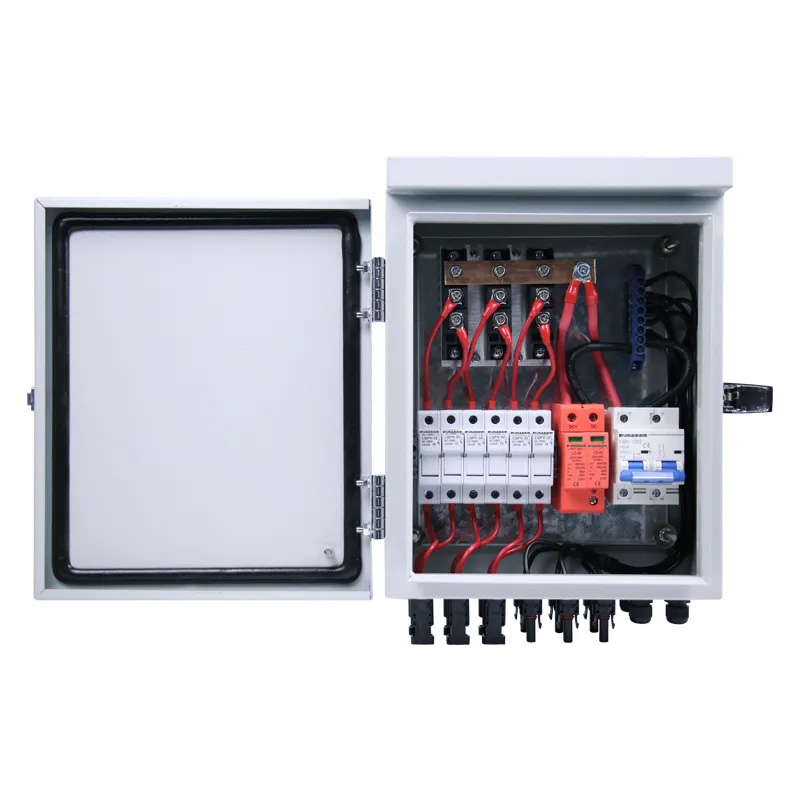
What Is a PV Combiner Box?
A PV combiner box is an electrical enclosure that aggregates multiple PV strings at a common bus, provides circuit protection for each string, and presents a single or multiple DC outputs (often via busbars) to the inverter or to a larger DC collection point. It is typically installed near the PV array to shorten string homeruns, reduce voltage drop, and centralize protection.
Why combiner boxes matter
- Safety: Individual string fusing and isolation lower the risk of faults escalating into fires.
- Maintainability: Centralized access simplifies inspection, testing, and part replacement.
- Cost & efficiency: Fewer homeruns and standardized wiring lower installation labor and copper usage.
- Monitoring: Smart combiners give real-time string current/voltage data to detect underperforming strings early.
Core Functions of a PV Combiner Box
1) String input combining
Multiple PV strings enter the enclosure through cable glands or MC-style connectors and terminate at string breakers or fuse holders. Downstream, these conductors are combined on a busbar to feed the output.
2) Overcurrent protection
Each string includes a dedicated DC-rated fuse or miniature circuit breaker (MCB). This limits fault current contributions from parallel strings and protects PV conductors per code and manufacturer data.
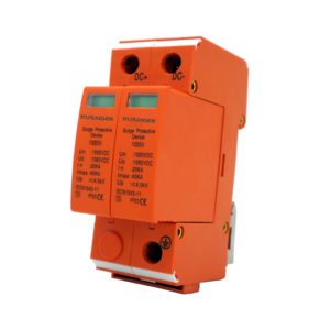
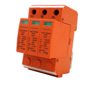
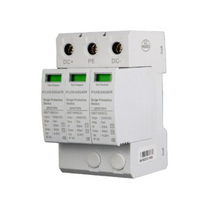
3) Surge protection (SPD)
Type 1 or Type 2 DC surge protective devices protect against overvoltage transients caused by lightning or switching events. Proper SPD selection considers system voltage (e.g., 1000 V or 1500 V DC), earthing scheme, and expected surge environment.
4) Isolation and disconnect
Many boxes integrate a DC isolator or knife switch to safely de-energize the output during service. The switch must be DC-rated for the maximum system voltage and current.
5) Grounding and bonding
Ground busbars and bonding jumpers ensure all metallic parts are at the same potential and provide fault-current return paths. Proper grounding reduces touch voltage hazards and improves SPD effectiveness.
6) Monitoring and communications
Smart combiners add Hall sensors or shunts for string current, temperature sensors, and communication modules (RS-485, Ethernet, or wireless). Data integrates with inverters, SCADA, or cloud platforms for analytics and alarms.
Internal Components
DC Fuses / String Breakers
Fast-acting gPV fuses sized at 1.25–1.56× Isc (string short-circuit current) are common. For breaker-based designs, use DC-rated MCBs with adequate interrupting capacity at system voltage.
Surge Protective Devices (SPD)
Choose SPD Type (1 or 2), Uc (continuous operating voltage), and protection mode (e.g., +/− to PE). Replaceable cartridges ease O&M.
Busbars
Tinned copper busbars sized for the combined current ensure low resistance and thermal stability. Clear creepage/clearance and insulation are required for 1500 V systems.
Disconnect Switch
Mechanically interlocked handles and visible break designs enhance safety. Verify load-break capability under worst-case DC conditions.
Enclosure
Outdoor units should meet at least IP65 (IEC) or NEMA 4/4X (UL) with UV-stable materials. Metal enclosures offer superior thermal performance; polycarbonate reduces weight and corrosion risk.
Monitoring Module
Shunt or Hall-effect measurement, MCU, and communications. Consider power budget (aux supply vs. self-powered), sampling rate, and accuracy.
| Parameter | Typical Range | Notes |
|---|---|---|
| System Voltage | 600 / 1000 / 1500 V DC | Match inverter and module specs |
| String Inputs | 4–24 per box | Utility boxes may support 24–32+ |
| Combiner Output Current | 80–400 A+ | Size busbars and lugs accordingly |
| Ingress Protection | IP65–IP67, NEMA 4/4X | Consider dust, rain, salt, UV |
| Impact Rating | IK08–IK10 | Mechanical robustness for field use |
| Operating Temp | -25 to 60 °C (typ.) | Derate per manufacturer |
Types of Combiner Boxes
Fused vs. Breaker-Based
Fused designs are compact and cost-effective; breaker-based designs allow simple reset and visible status without opening fuse holders. Choice often depends on maintenance philosophy and ambient conditions.
With vs. Without Monitoring
Monitoring adds CapEx but cuts OpEx via faster fault localization, reduced truck rolls, and optimized cleaning cycles based on performance ratios.
Indoor vs. Outdoor
Outdoor (IP65/67) combiner boxes dominate ground-mount and rooftop sites; indoor variants appear in sheltered plant rooms.
Residential, C&I, Utility
Residential boxes are smaller (4–6 strings), C&I mid-size (8–16), and utility boxes large (16–32+), often with higher voltage ratings (up to 1500 V DC) and advanced monitoring.
Design Considerations
Sizing string protection
Fuse size must exceed worst-case operating current but interrupt safely under fault. Reference module Isc at STC × correction factors (irradiance/temperature) and code tables.
Voltage rating & creepage/clearance
At 1500 V DC, maintain adequate spacing, insulation barriers, and conformal coatings where needed. Observe pollution degree and overvoltage category.
Thermal management
Combine current generates heat at busbars and protection devices. Prefer light-colored enclosures, sunshades, and internal layouts with airflow paths. Consider thermal imaging during FAT/SAT.
Environmental resilience
- UV-resistant plastics, powder-coated metals
- Breather vents for pressure equalization to avoid condensation
- Gasket materials rated for temperature and chemical exposure
Certifications & standards
Specify compliance with relevant standards (e.g., IEC 61439, IEC 60364, UL 1741, UL 508A). Ensure third-party certification and traceable test reports.
Cable entry and workmanship
Use strain relief, gland sizing per cable OD, and ferrules where applicable. Maintain bend radii and torque per datasheets with a torque wrench log.
How to Select the Right PV Combiner Box
- Define system voltage and max string current. This sets fuse rating, SPD Uc, and clearances.
- Count parallel strings per MPPT/inverter. Size inputs and output busbar accordingly.
- Pick protection philosophy. Fuse vs. breaker, number and type of SPDs, disconnector rating.
- Match environment. Ingress and impact rating, UV, salt-mist, ammonia for agri-PV.
- Decide on monitoring. Measure per-string current for faster O&M.
- Serviceability. Space for tools, hinged panels, clear labeling, spares policy.
Installation Guide
Pre‑installation checks
- Verify nameplate ratings match design (Vdc, Idc, number of inputs).
- Inspect enclosure for transit damage; check gaskets and latches.
- Confirm accessories: fuses, SPD cartridges, labels, torque chart.
Mounting
Mount vertically on a rigid structure with shaded exposure if possible. Maintain working clearances and height for safe operation of disconnects.
Wiring
- De-energize and lock out sources. Use LOTO procedures.
- Route strings through glands; maintain polarity; land to fuse holders/breakers.
- Bond EGC to ground busbar; verify continuity.
- Connect output conductors to busbar lugs; torque to spec; record in log.
Commissioning tests
- Continuity and insulation resistance (megger) per voltage class.
- Polarity verification at output; ensure disconnect operates smoothly.
- For smart boxes: communications check and baseline current per string.
Maintenance & Inspection
Implement a preventive maintenance (PM) plan with intervals adjusted for climate, dust, and lightning exposure.
Routine tasks
- Visual checks for discoloration, corrosion, ingress, and loose hardware.
- Thermal scan during peak irradiance to locate overheating terminations.
- Torque verification annually or per manufacturer guidance.
- SPD status indicator inspection; replace cartridges when flagged.
Records & KPIs
Track string currents, number of blown fuses, SPD replacements, temperature excursions, and enclosure openings. Use trends to optimize cleaning and vegetation control.
Common Problems & Troubleshooting
Blown fuses / tripped breakers
Likely causes: string short, module bypass diode failure, or reverse polarity. Isolate the string, measure Voc/Isc, and compare against neighbor strings and baseline.
SPD end-of-life
Frequent surge events or mis-specified Uc. Verify earthing and bonding; consider Type 1+2 for high lightning density sites.
Loose terminations & hot spots
Thermal cycling loosens lugs; use torque paint and re-torque schedule. Replace heat-damaged parts and investigate conductor sizing.
Ingress and condensation
Check gasket integrity, cable gland tightness, and add breather vents. Use desiccant packs in humid climates.
Monitoring communication faults
Check power to the monitoring module, verify addressing/termination on RS‑485, and validate network settings. Keep a golden configuration file.
Large-Scale Project Best Practices
- Architecture: Decide centralized vs. decentralized collection considering terrain and trench costs.
- Standardization: Reuse a qualified BOM across blocks to simplify spares and training.
- SCADA integration: Map alarms and string currents; implement automated underperformance alerts.
- Constructability: Pre-terminated harnesses, color-coded labels, and QR-linked as-builts reduce errors.
- Quality control: FAT at factory + SAT on site with documented torque values and IR photos.
Future Trends
- Smarter per-string analytics with edge AI for anomaly detection.
- Enhanced arc-fault detection and shutdown integration.
- Higher-voltage, more compact busbar designs with better thermal paths.
- Hybrid readiness for DC-coupled storage interfaces.
Frequently Asked Questions
Do I need a combiner box for small residential systems?
Microinverter and DC optimizer systems may not require traditional combiners. For string inverters with multiple strings, a small combiner simplifies protection and wiring.
How do I size fuses for 1500 V systems?
Use gPV fuses rated for at least the system voltage and size them per the module Isc with appropriate correction factors; consult manufacturer tables.
Which SPD type should I choose?
Type 1 is recommended where direct lightning currents are possible; Type 2 fits many standard sites. Ensure Uc exceeds maximum DC operating voltage and match earthing.
Metal vs. polycarbonate enclosure?
Metal handles heat better and offers robustness; polycarbonate resists corrosion and is lighter. Choose based on climate, mechanical risk, and cost.
Downloadable Checklists