The Ultimate Guide to Photovoltaic Combiner Boxes: Functions, Structure, and Key Components
Practical, technical guide for PV installers, designers, purchasers and O&M teams.
1. Introduction: What is a Combiner Box?
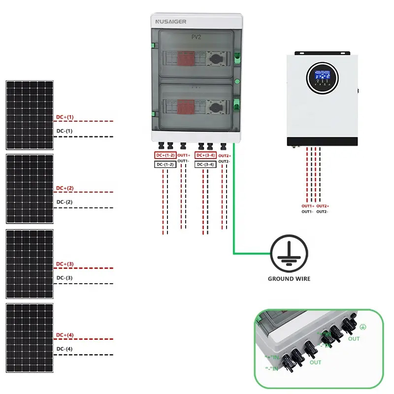
A photovoltaic (PV) combiner box is an electrical enclosure that aggregates multiple PV string outputs into a smaller number of conductors toward the inverter or downstream DC distribution. It centralizes string-level protection, simplifies wiring, and often houses monitoring and surge protection functions. Combiner boxes can be located on rooftops, near arrays, or in central infield points for utility systems.
2. Core Functions and Benefits
Primary roles of a combiner box include:
- String aggregation — merging currents from several strings to reduce cable runs and simplify connections.
- Overcurrent protection — fusing or breakers on each string to isolate faults.
- Surge protection — SPDs to reduce damage from lightning and switching transients.
- Disconnects — safe isolation for maintenance with visible disconnector handles in some models.
- Monitoring — optional string-level current/voltage/temperature monitoring for rapid fault detection.
- Safety & compliance — facilitates meeting code requirements (e.g., NEC 690 in the U.S.).
Why it matters: Proper combiner design reduces O&M time, minimizes energy losses, and significantly reduces fire risk by isolating faulty strings early.
3. Internal Structure and Typical Components
A well-designed combiner box consists of mechanical and electrical subsystems. The electrical layout typically includes input terminals, fuses or DC circuit breakers, a busbar or busbar assembly, surge protective devices, a main output terminal, and optional monitoring electronics.
3.1 Input interfaces
Input side uses PV-rated cable glands or MC4-style connectors, strain reliefs, and clearly marked string terminals. Inputs are often PV+ and PV− per string.
3.2 Overcurrent protection
String fuses (blade or cylindrical) or DC-rated miniature circuit breakers protect each string. Fuse sizing follows code rules (e.g., NEC 690.8 requires 125% of Isc for fuse ratings in certain cases) — always check local codes.
3.3 Busbar & wiring
A busbar (often tin-plated copper) collects string currents. Busbar sizing accounts for steady state current plus thermal derating and short-circuit withstand. Mechanical design ensures secure terminations with specified torque.
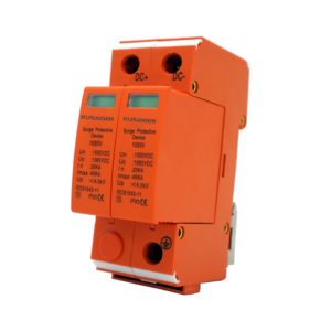
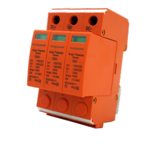
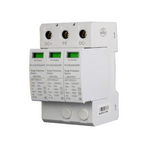
3.4 Surge Protective Devices (SPDs)
SPDs on DC inputs and sometimes on output protect against lightning and transient surges. Choose SPDs with appropriate Uc (maximum continuous operating voltage) and In/Imax ratings for PV DC systems (600V, 1000V, 1500V markets vary).
3.5 Disconnects & DC switches
Some boxes include a visible DC disconnect for isolation before maintenance. In larger systems, remote controlled DC disconnects can be integrated.
3.6 Monitoring modules
String-level monitoring modules (current sensors, shunts, or hall-effect sensors) paired with communication (RS485/Modbus, CAN, or Ethernet) allow per-string diagnostics essential for fast O&M.
3.7 Enclosure & environmental protection
Outdoor combiner boxes must meet IP65/66 or NEMA4X ratings. Material choices include powder-coated steel, stainless steel, or UV-stabilized polycarbonate for different environments.
4. Types and Configurations
Combiner boxes are available in multiple topologies:
- String Combiner (standard): 4–24 string inputs, simplest, common in commercial rooftops.
- Advanced Combiner (smart): includes string-level monitoring and remote communications.
- DC Junction Enclosure: heavy-duty box with busbar assemblies for utility arrays with many inputs.
- AC Combiner / Distribution: used at inverter output side to combine AC circuits (less common term “combiner” in AC side but still used).
Choose the configuration based on string count, distance to inverter, monitoring needs, and environmental exposure.
5. Selection Criteria — How to Choose the Right Combiner Box
Key selection checklist:
- Input count: number of strings now and planned expansion.
- Voltage class: match the maximum system Voc (600V/1000V/1500V DC systems).
- Current rating: per string and summed output; busbar and terminals rated accordingly.
- Protection type: fuse vs breaker; consider maintenance & replacement logistics.
- SPD requirements: lightning zone, site risk, and Uc/In ratings.
- Monitoring & communications: Modbus/RS485, remote telemetry needs.
- Ingress & corrosion protection: IP/NEMA rating, material selection for coastal/industrial sites.
- Mounting & space constraints: rooftop vs ground-mount, weight, and footprint.
- Approvals: UL/IEC/CE/TÜV depending on market.
Tip: When in doubt, buy a combiner box rated higher (voltage/current) with room for expansion — it’s cheaper than replacing mid-project.
6. Installation Best Practices
Good installation reduces risk of arcing, water ingress, and long-term failure. Consider these practical steps:
6.1 Location & mounting
Install combiner boxes as close to the array as practical to minimize DC cable lengths and reduce voltage drop. Ensure boxes are mounted on non-corrosive brackets and at accessible heights for technicians.
6.2 Cable management
Use proper cable glands rated for PV cables; avoid sharp bends near terminations; create clear segregation between DC+ and DC− and keep conductors tidy to reduce inductance and risk of accidental contact.
6.3 Torque procedures
Follow manufacturer torque specs for all terminations. Loose bolts are one of the leading causes of hot joints and failures. Document torque values during commissioning.
6.4 Grounding & equipotential bonding
Bond the combiner enclosure, negative bus, and any metal conduit to the site grounding system per local code. Ensure low impedance bonding for lightning protection.
6.5 Labeling & documentation
Label each string input, fuse, and output clearly. Keep wiring schematics and part lists in a weatherproof pouch inside the box or at the O&M office.
7. Protections: Fuses, Breakers, SPDs, AFCI, and Grounding
Protection design is at the heart of combiner functionality:
7.1 String-level overcurrent protection (fuses vs breakers)
Fuses are economical and widely used (cylindrical or blade). DC-rated breakers provide resettable protection and ease of maintenance but are larger and more costly. Sizing rules often follow code: select fuse nominal > Isc × safety factor but < conductor ampacity limit — consult NEC and regional rules.
7.2 Surge Protective Devices (SPD)
DC SPDs protect equipment from transient overvoltage. For PV systems, use SPDs rated for DC operation at system Voc. Consider Type 1+2 combined SPDs for sites in high lightning risk zones.
7.3 Arc fault detection (AFCI)
Some jurisdictions require PV arc-fault detection devices — arc faults in DC strings can cause fires. AFCI solutions detect arcing signatures and isolate the circuit. Evaluate code requirements and choose combiner boxes with AFCI integration if required.
7.4 Ground fault protection
PV systems can develop ground faults; combiner boxes sometimes host ground-fault indicators or monitoring for DC insulation checks. Ensure integration with inverter’s ground-fault detection scheme where applicable.
8. Testing, Commissioning and Verification
Commissioning combiner boxes ensures safe, reliable operation:
8.1 Pre-energization checks
- Verify polarity and string labeling
- Confirm fuse/breaker ratings and spare inventory
- Inspect SPDs installed and connected to ground
- Record torque values and physical condition
8.2 Electrical tests
- Continuity & low-resistance measurement: Verify milliohm contacts on busbars and output conductors.
- Insulation resistance test: Use a megger to check isolation between conductors and ground as per manufacturer and code.
- Thermographic baseline: With system at operating conditions (or simulated load), capture IR images of all terminations for baseline.
8.3 Functional verification
Confirm string monitoring reports expected signals, check SPD fault indicators, and validate disconnect operation. Document everything in commissioning reports.
9. Operation, Monitoring and Maintenance
Routine O&M ensures combiner reliability:
9.1 Monitoring approaches
Options: no monitoring (basic), local LED indicators, or full telemetry via Modbus/RS485 or wireless. Smart combiner boxes allow central logging and alarms — highly recommended for commercial and utility sites.
9.2 Scheduled inspections
- Monthly visual checks (enclosure, seals, cable glands)
- Quarterly SPD and fuse inspection
- Annual thermographic scanning and torque verification
- 3–5 year insulation resistance testing
9.3 Spare parts & maintenance kit
Keep spare fuses/breakers, replacement SPDs, seal gaskets, and cable glands on site to minimize downtime.
10. Common Faults and Troubleshooting
Frequent issues and remedies:
10.1 Overheating at terminations
Cause: loose bolts, corrosion, undersized conductors. Fix: de-energize, retorque to spec, clean contacts, replace if degraded, thermograph to confirm.
10.2 Frequent fuse blowing
Cause: ground fault, shorted module, reverse polarity, or damaged insulation. Diagnose: isolate strings, measure Isc, inspect modules/connectors; replace fuse only after root cause fixed.
10.3 SPD failures / burned SPD
Cause: severe surge event or poor grounding. Action: replace SPD with correct rating and inspect ground conductor paths; consider adding a higher-rated SPD architecture.
10.4 Water ingress
Cause: degraded gaskets, wrong ingress rating, cable gland failure. Solution: replace gaskets, use proper IP-rated glands, and dry out and inspect internal components.
11. Practical Case Studies
Case Study A — Rooftop Commercial Array (100 kW)
Problem: Intermittent drop in one inverter string. Investigation revealed a partially corroded fuse holder leading to high resistance and thermal cycling. Solution: Replace holder, upgrade to tinned copper busbar, add local LED monitoring to detect future failures quickly. Result: uptime improved and O&M visits reduced by 40%.
Case Study B — Utility-Scale Array (10 MW)
Problem: Lightning season created repeated SPD failures on combiner boxes. Root cause: long ground conductor runs and inadequate earthing mesh. Solution: redesign ground grid near combiner yard, install Type 1+2 SPDs, shorten ground leads. Result: SPD survivability increased significantly and downstream inverter failures decreased.
12. Standards, Certifications and Regulatory Compliance
Commonly referenced standards and guidance:
- NEC (National Electrical Code) Article 690: PV system requirements in the US.
- IEC 61730 / IEC 62548: PV module and array guidelines.
- UL 1741: Inverter and PV balance-of-system approvals (US market).
- IEC 61643-31: SPD requirements for PV applications.
When procuring combiner boxes, request manufacturer test reports, UL/IEC certifications and environmental test data (salt spray, UV aging) for the intended location.
13. Procurement & Total Cost Considerations
Don’t buy on price alone. Consider:
- Warranty & support terms
- Quality of internal components (busbar plating, fuse holders)
- Ease of field replacement and spare availability
- Long-term O&M costs — monitored systems often pay back in reduced downtime
13.1 Example cost breakdown
| Item | Consideration | Impact |
|---|---|---|
| Base combiner enclosure | IP65 plastic vs stainless NEMA4X | Initial cost vs longevity in coastal sites |
| Monitoring kit | Modbus logging & current sensors | Higher upfront, much lower O&M cost |
| SPD | Type 2 vs Type 1+2 combined | Protection level & replacement freq. |
14. Conclusion & Practical Checklists
Photovoltaic combiner boxes are a key node in PV systems — when properly selected, installed and maintained, they increase safety and reduce O&M costs. Below are compact checklists for quick use.
Pre-purchase checklist
- Voltage rating matches system Voc
- String count & expansion capability
- SPDs and protection devices rated for site
- Ingress protection meets site environment
- Certifications & manufacturer support contract
Commissioning checklist
- Torque values recorded
- Insulation resistance verified
- Thermographic baseline recorded
- Monitoring & alarms validated
Maintenance checklist
- Monthly visual & LED indicator check
- Quarterly SPD inspection
- Annual thermography & retorque
- 3–5 year insulation & electrical testing